Note
Go to the end to download the full example code.
Feedback algorithm example
This script calculates phase patterns for a phase-modulating liquid crystal on silicon (LCOS) spatial light modulator (SLM) to create accurate light potentials by modelling pixel crosstalk on the SLM and using conjugate gradient (CG) minimisation with camera feedback (see https://doi.org/10.1038/s41598-023-30296-6).
Using this script, it should be easy to switch between the different patterns from our publication, turn on pixel crosstalk modelling and switch between the fast Fourier transform (FFT) and the angular spectrum method (ASM) to model the propagation of light.
Importing modules
import os
import time
import numpy as np
import matplotlib.pyplot as plt
from mpl_toolkits.axes_grid1 import make_axes_locatable

from hologradpy import patterns as p
from hologradpy import error_metrics as m
from hologradpy import calibrate_slm as clb
from hologradpy import torch_functions as tfn

from examples.experiment import Params, Camera, SlmDisp
Here, we determine which computing hardware to use (CPU or GPU) and create instances from our custom hardware classes.
device = tfn.check_device(verbose=True)   # Check for GPU

pms_obj = Params()
cam_obj = Camera(np.array([960, 1280]), 3.75e-6, bayer=True)    # Create instance of camera class
slm_disp_obj = SlmDisp(np.array([1024, 1280]), 12.5e-6)         # Create instance of SLM class
Initializing the camera feedback algorithm
Parameters for the phase-retrieval algorithm:
npix = 1024                 # Number of pixels on SLM (npix * npix)
propagation_type = 'fft'    # Propagation Type
optimizer = 'cg'            # Optimizer
loss_fn = 'amp'             # Loss function used during optimization
fft_shift = True            # Perform FFT shift?
precision = 'single'        # Computational precision
pixel_crosstalk = False     # Model pixel crosstalk?
pix_res = 1                 # Subsampling factor of each SLM pixel
detect_vortices = False     # Detect vortices before the first camera feedback iteration?
threshold_vtx = 0.05        # Vortices are only detected in regions brighter than threshold (1 is maximum)

# Path containing a previously calculated affine transform to calibrate the camera.
tf_path = pms_obj.data_path + '23-08-29_18-42-53_torch_camcal/'

calc_transform = True           # Calculate new transform?
measure_slm_intensity = False   # Measure the constant intensity at the SLM (laser beam profile)?
measure_slm_phase = False       # Measure the constant phase at the SLM?
Parameters for the initial SLM phase guess, the target light potential and the signal region:
guess_type = 'guess'                                            # Use analytical phase guess
phase_angle = int(-npix // 4)                                   # Offset of the target light potential to the optical
                                                                # axis in x- and y-direction in Fourier pixels to
                                                                # calculate the gradient of linear phase.
linear_phase = np.array([phase_angle + 2, phase_angle - 2])   # Linear term of the initial phase guess
quad_phase = np.array([4.7e-4, 0.5])                            # Quadratic term of the initial phase guess

# Target Pattern
pattern = 'spot_array'                                          # Name of the target light potential
mask_pos = int(phase_angle)                                     # Offset of the target light potential to the optical
                                                                # axis in x- and y-direction in Fourier pixels
target_width = int(npix // 2)                                   # Size of the target light potential
target_blur = 2                                                 # Width of the blurring kernel for the target light
                                                                # potential
Parameters for the camera feedback algorithm:
cam_name = 'before'                     # Name of camera
slm_disp_type = 'lut'                   # SLM display mode
iter_fb = 10                            # Number of camera feedback iterations
iter_cg = 50 * np.ones(iter_fb)         # Number of CG iterations per feedback iteration
alpha = np.ones(iter_fb)                # Feedback gain parameter
exp_time = 200                          # Exposure time of camera in microseconds
n_frames_avg = 10                       # Number of camera pictures taken to average
feedback_blur = 0                       # Size of Gaussian blurring for camera feedback
Defining the blurring kernel to model pixel crosstalk:
if pixel_crosstalk is True:
    extent = 3                          # Extent of crosstalk kernel in SLM pixels
    q = 2.3                             # Crosstalk kernel order
    sigma = 0.92 / slm_disp_obj.pitch   # Crosstalk kernel width
    kernel_ct = p.pixel_ct_kernel(slm_disp_obj.pitch, pix_res, extent, q, sigma)
else:
    kernel_ct = None
Inputs for the angular spectrum method:
# Number of pixels of zero-padded SLM plane
if propagation_type == 'asm':
    npix_pad = int(pms_obj.lens_aperture // pms_obj.slm_pitch)
else:
    npix_pad = 2 * npix

npix_tot = npix_pad * pix_res                   # Total number of pixels (npix_tot * npix_tot)
extent_lens = npix_pad * slm_disp_obj.pitch     # Spatial extent of computational lens plane [m]
pd1 = pms_obj.fl                                # Distance from SLM plane to lens plane [m]
pd2 = pms_obj.fl                                # Distance from lens plane to camera plane [m]
Determine which data to save.
save = False                    # Save camera images?
convergence = False             # Save convergence of CG algorithm?
n_save = 5                      # Save every xx th CG iteration
iter_plot = [1, 2, 13, 14, 15]  # List of feedback iterations to save CG convergence

# Create folder to save data
date_saved = time.strftime('%y-%m-%d_%H-%M-%S', time.localtime())
path = pms_obj.data_path + date_saved + '_' + os.path.splitext(os.path.basename(__file__))[0] + '_' + pattern
os.mkdir(path)
Measuring the constant intensity and phase at the SLM
Measuring the constant intensity and phase at the SLM is crucial for accurate experimental results - see the supplementary information of our publication for details.
if measure_slm_intensity is True:
    i_path = clb.measure_slm_intensity(slm_disp_obj, cam_obj, pms_obj, 30, 32, 10000, 256, 300)
    pms_obj.i_path = i_path
if measure_slm_phase is True:
    phi_path = clb.measure_slm_wavefront(slm_disp_obj, cam_obj, pms_obj, 30, 16, 64, 40000, 256, roi_min_x=2,
                                         roi_min_y=2, roi_n=26)
    pms_obj.phi_path = phi_path
Using the functions above, this is our constant field at the SLM after upscaling it to the native resolution of the SLM:

Defining the target light potential
The patterns.Hologram class contains pre-defined patterns from our publication. It creates
the upscaled measured constant SLM phase and intensity,
the initial SLM phase guess,
the target intensity pattern,
and the signal region.
Feel free to define the arrays above yourself - using the patterns.Hologram class is not mandatory.
holo = p.Hologram(slm_disp_obj, pms_obj, pattern, npix, npix_pad=npix_pad, pix_res=pix_res, phase_guess_type=guess_type,
                  linear_phase=linear_phase, quadratic_phase=quad_phase, slm_field_type='measured',
                  propagation_type=propagation_type, target_position=mask_pos, target_width=target_width,
                  target_blur=target_blur)
Here is our target light potential, a Gaussian spot array, and the signal region:

The target is shifted away from the center to avoid the zeroth order diffration spot. The phase retrieval algorithm only optimises for the intensity inside the signal region.
We use an analytic initial SLM phase guess consisting of a quadratic and a linear phase term. The quadratic phase term depends on the size and the aspect ratio of the target pattern while the linear term depends on the position of the pattern with respect to the optical axis. The initial phase guess defined here looks like this:

Creating a virtual SLM object
This is a digital twin of the experimental Fourier holography setup. The forward method of VirtualSlm takes an
SLM phase pattern, models pixel crosstalk on the SLM and the propagation of light from the SLM to the camera. It
returns the electric field at the image plane.
# Create SLM mask to set unused pixels to zero
slm_mask = np.zeros((npix, npix))
slm_mask[pms_obj.crop:-pms_obj.crop, pms_obj.crop:-pms_obj.crop] = 1

# Pixel pitch in the Fourier plane (padded) [m]
img_pitch = pms_obj.wavelength * pms_obj.fl / (slm_disp_obj.pitch * slm_disp_obj.res[0] * 2)
xf = -256 * img_pitch  # ToDO: Explain this.

# Create virtual SLM object
slm_obj = tfn.VirtualSlm(slm_disp_obj, pms_obj, holo.phi_init, npix_pad, npix=npix, e_slm=holo.e_slm,
                         kernel_ct=kernel_ct, pix_res=pix_res, propagation_type=propagation_type,
                         extent_lens=pms_obj.lens_aperture, pd1=pd1, pd2=pd2, xf=xf, device=device, slm_mask=slm_mask,
                         precision=precision, fft_shift=fft_shift).to(device)
Camera calibration
Here, we calculate the affine transformation matrix between camera coordinates and image plane coordinates. This is important to compare the simulated light potential to the captured camera image.
if calc_transform is False:
    tf = np.load(tf_path + 'tf.npy')
    itf = np.load(tf_path + 'itf.npy')
else:
    # ToDO: Control over checkerboard position missing.
    tf, itf = tfn.camera_calibration(slm_obj, slm_disp_obj, cam_obj, pms_obj, save=True, exp_time=1000,
                                     checkerboard_rows=16, checkerboard_columns=12, checkerboard_square_size=30)
This is the result:

Note that the zeroth-order diffraction spot is now located in the center of the computational image plane on the right hand side.
Running the camera feedback algorithm
First, we create an object from torch_functions.PhaseRetrieval which sets the phase retrieval method. By default,
torch_functions.PhaseRetrieval performs conjugate gradient minimisation using an amplitude-only cost function (see
https://doi.org/10.1364/OE.22.026548).
This phase retrieval method is then used iteratively by the camera feedback algorithm (see https://dx.doi.org/10.1088/0953-4075/48/11/115303).
Before running the camera feedback algorithm, we set the phase of the virtual SLM , slm_obj, with the initial
phase guess. The phase pattern of slm_obj might have been modified by the torch_functions.camera_calibration
function.
phase_retrieval_obj = tfn.PhaseRetrieval(slm_obj, n_iter=int(iter_cg[0]), i_tar=holo.i_tar, signal_region=holo.sig_mask,
                                         save=convergence, n_save=n_save)

if propagation_type == 'asm':
    # Modify the initial phase pattern on our virtual SLM if the ASM is used.
    slm_obj.set_phi(holo.phi_init - slm_obj.asm_obj.phi_q_native)
else:
    phase_retrieval_obj.slm_obj.set_phi(holo.phi_init)

# Run camera feedback algorithm
output = tfn.camera_feedback(phase_retrieval_obj, slm_disp_obj, cam_obj, tf, itf, iter_fb=iter_fb, iter_cg=iter_cg,
                             detect_vortices=detect_vortices, threshold_vtx=threshold_vtx, n_save=n_save,
                             n_avg=n_frames_avg, exp_time=exp_time, fb_blur=feedback_blur, alpha=alpha,
                             convergence=convergence, iter_convergence=iter_plot, path=path)

phi, img, M, T, [rmse, psnr], [rmse_conv_sv, rmse_pred_conv_sv, eff_conv_sv, n_conv_sv] = output
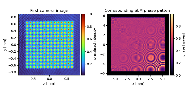
After the first 50 CG iterations, the optimised SLM phase pattern is displayed on the device and a camera image is taken:
Here, we only show the signal region on the camera. The experimental errors in the camera image are greatly reduced after 10 camera feedback iterations with 50 CG iterations each:

# Transfer electric field in the image plane to CPU
e_out = tfn.gpu_to_numpy(slm_obj())

# Calculate intensity pattern of the simulated light potential
i_out = np.abs(e_out) ** 2

# Calculate phase pattern of simulated light potential
phi_out = np.angle(e_out)

# Calculate efficiency
eff = m.eff(holo.sig_mask, i_out)
print('Efficiency of the simulation:', eff * 100, '%')
Plotting
px = 1 / plt.rcParams['figure.dpi']
fig0, axs0 = plt.subplots(figsize=(800*px, 400*px))
plt.plot(np.arange(1, iter_fb + 1), rmse * 100, 'k*', label='RMS error')
plt.title('Experimental RMS error vs iteration number')
plt.xlabel('feedback iteration number')
plt.ylabel('experimental RMS error [%]')

plt.figure()
plt.plot(psnr, 'go', label='PSNR')
plt.title('Experimental PSNR vs iteration number')
plt.xlabel('experimental iteration number')
plt.ylabel('PSNR [dB]')
We can now plot the rms error of the camera images after each feedback iteration:

The feedback algorithm lowered rms error from ~12 % to ~1.6 %.
plt.figure()
plt.imshow(i_out, cmap='turbo')
plt.title('Simulated light potential')

plt.figure()
plt.imshow(phi_out, cmap='magma')
plt.title('Phase of simulated light potential')

plt.figure()
plt.imshow(img[..., -1].squeeze(), cmap='turbo')
plt.title('Camera image')
plt.savefig(path + '//img.pdf', dpi=1200)

target_norm = T[..., 0].squeeze() * tfn.camera_feedback.sig_mask_tf
mask_target = target_norm > 0.1 * np.max(target_norm)
target_norm = target_norm / np.sum(target_norm[mask_target])

img_norm = img[..., 3].squeeze() * mask_target
img_norm = img_norm / np.sum(img_norm)
diff_img = (img_norm - target_norm) * mask_target

plt.figure()
plt.imshow(diff_img, cmap='seismic', vmin=-np.max(np.abs(diff_img)), vmax=np.max(np.abs(diff_img)))
We can investigate the convergence of the phase retrieval algorithm in-between feedback iterations by saving intermediate phase patterns, displaying them on the SLM and capturing the resulting camera image. This allows us to see when the rms error of the camera image converges to determine the number of CG iterations needed per feedback iteration.
# Plot and save convergence graphs
if convergence is True:
    plt.figure('rmse')
    x = min(iter_plot)
    for i in range(len(iter_plot)):
        plt.figure('rmse')
        x = np.linspace(iter_plot[i] - 1 + 1 / iter_cg[iter_plot[i] - 1],
                        iter_plot[i] - 1 + n_conv_sv[i] * n_save / iter_cg[iter_plot[i] - 1], n_conv_sv[i])
        line_exp, = plt.plot(x, rmse_conv_sv[i] * 100, '-', color='C0')
        line_pred, = plt.plot(x, rmse_pred_conv_sv[i] * 100, '--', color='r')

        plt.figure('eff')
        plt.plot(x, eff_conv_sv[i] * 100, '-', color='C1')

    line_exp.set_label('experiment')
    line_pred.set_label('predicted')

    plt.figure('rmse')
    plt.plot(np.arange(1, iter_fb + 1), rmse * 100, 'k*', label='RMS within 50% of max. intensity')
    plt.legend()
    plt.xlabel('CG iterations')
    plt.ylabel('RMS error [%]')
    plt.grid()
    plt.savefig(path + '//rmse.pdf', bbox_inches='tight', dpi=600)

    plt.figure('eff')
    plt.xlabel('CG iterations')
    plt.ylabel('Predicted efficiency [%]')
    plt.grid()
    plt.savefig(path + '//efficiency.pdf', bbox_inches='tight', dpi=600)
Saving data
Saving data to the hard drive.
if save is True:
    np.save(path + '//lin_phase', linear_phase)
    np.save(path + '//quad_phase', quad_phase)
    np.save(path + '//tf', tf)
    np.save(path + '//itf', itf)
    np.save(path + '//T', T)
    np.save(path + '//npix', npix)
    np.save(path + '//npix_pad', npix_pad)
    np.save(path + '//pix_res', pix_res)
    np.save(path + '//M', M)
    np.save(path + '//img', img)
    np.save(path + '//phi', phi)
    np.save(path + '//prop', propagation_type)
    np.save(path + '//exp_time', exp_time)
    np.save(path + '//kernel_ct', kernel_ct)

    np.save(path + '//rmse', rmse)
    np.save(path + '//eff', eff)
    np.save(path + '//psnr', psnr)

    np.save(path + '//rmse_conv_sv', rmse_conv_sv)
    np.save(path + '//rmse_pred_conv_sv', rmse_pred_conv_sv)
    np.save(path + '//eff_conv_sv', eff_conv_sv)
    np.save(path + '//n_conv_sv', n_conv_sv)
    np.save(path + '//iter_plot', iter_plot)

    np.save(path + '//a_tar', holo.a_tar)
    np.save(path + '//sig_mask', holo.sig_mask)
    np.save(path + '//n_save', n_save)
    np.save(path + '//iter_fb', iter_fb)